

 |
|
Advantages – Zero Air Loss
|
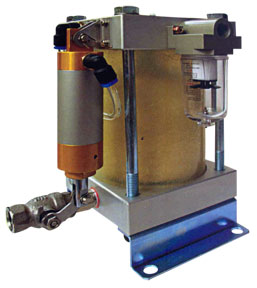
Installation & Operation Connect the condensate outlet to the inlet of the Autodrain located at the bottom through a Strainer as per diagram. Remember to install a return line to prevent Air Lock. As the condensate fills up the chamber, the float will start to rise.On the float there is a magnet which when lifted to a pre-determined level will activate a counter magnet which is located in the center shaft. The counter magnet will activate a pneumatic valve to open and lift a pneumatic a cylinder that will open a discharge valve. The pressure from the compressed air will push the condensate out through the discharge outlet. And when the water level drops, the float will drop and thus activating the counter magnet again which will close the valve and thus the discharge outlet is automatically closed again. Since the water level is always higher than the discharge outlet, there will be no Air Losses. |
|
|---|---|---|
|
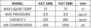
Technical Specification
 |
||
 |
Proposed Installation Location |
|
AUTO DRAIN
Zero Loss Auto Drain – Model KAT 500 (pdf file)
| Operation Principle And Structure | ||
 |
||
|
Advantages – Zero Air Loss
|
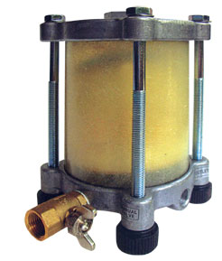
Installation & Operation Connect the condensate outlet to the inlet of the Autodrain located at the top through a Strainer as per diagram. Then connect the discharge to the drains. Should the height of the condensate outlet be too low, then connect to the other inlet located at the bottom but remember to install a return line to prevent Air Lock. As the condensate fills up the chamber, the float will start to rise and thus exposing the discharge outlet. The pressure from the compressed air will push the condensate out through the discharge outlet. And when the water level drops, the discharge outlet is automatically closed again. Since the water level is always higher than the discharge outlet, there will be no Air Losses. |
|
|---|---|---|
|
Technical Specification
 |
||
 |
Proposed Installation Location
|
